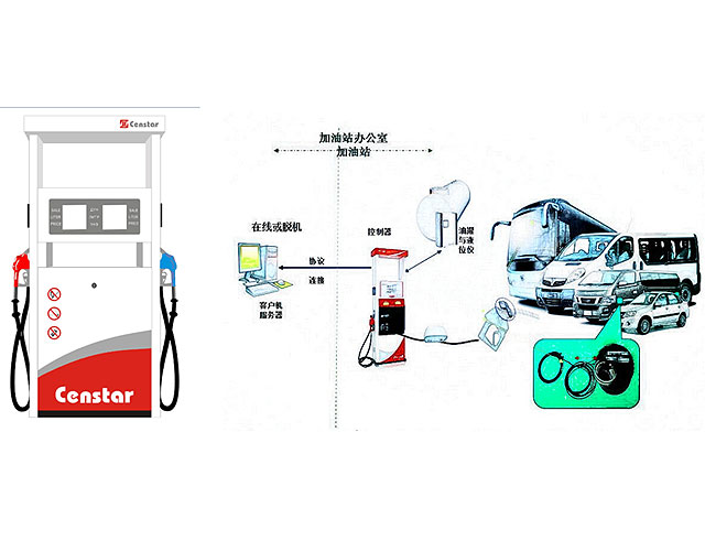
diesel vapour recovery system

Vapor Recovery System Test Equipment Franklin Fueling
Hose Retriever System; Anti Kink Hose Clamp; Hose Support; Hose Retractor; Hose Accessories and Spare Parts; Hoses and System Accessories; Vapor Recovery System Test Equipment

Standards and Best Practice Guidelines for Vapour Recovery
Section 6 sets out best practice guidelines for the design and operation of vapour recovery systems. 2 Interpretation and definitions Where the Regulation and these Standards and Guidelines differ on any point, the ‘Petrol’ includes petrol blends, but not diesel.

Gasoline Diesel Rack Loading and Operating Procedure 8
GASOLINE/DIESEL RACK LOADING AND OPERATING PROCEDURE Authorized by: Operations Department Moc # 03 06 12 412 033 Carr 8/9/12 Page 3 of 18 GENERAL GUIDELINES 1. Turn off all electronic devices (cell phones and CB radios) before entering the terminal entrance. 2. NO SMOKING OR OPEN FLAMES ARE PERMITTED AT THE TERMINAL. 3. Speed Limit is 5 mph. 4.

Stage 1 Vapor Recovery Test Results Form
This Stage 1 Vapor Recovery Test Results report will be considered incomplete unless the required signature is provided. I certify that I have been authorized by the owner or operator of the GDF site listed in Part I of this form to test the Stage I Vapor Recovery System and submit the test results to the CT DEEP on their behalf.

Vapor Recovery Developments in Emission Standards and
Vapour Recovery Systems and Vapour Combustion Systems Legislation introduced into Europe In the 1990s Covering Gasoline Loading Operations. EU Directive 94/EU/63 Other Countries Followed : Far East / Middle East / Russia Environmental legislation driver for other emission controls legislation.

Standards and Best Practice Guidelines for Vapour Recovery
The requirement to fit vapour recovery equipment depends on petrol throughput (the quantity of petrol dispensed per annum) and the location of the service station. Even if the petrol service station throughput subsequently decreases, continued operation of the vapour

Vapor Recovery Systems Suppliers ThomasNet
ISO 9001:2000 certified custom manufacturer of vapor recovery systems. Vapor recovery systems include halon gas recovery systems. Capabilities of halon gas recovery systems include halon gas condensing into liquid & recovery. Specifications include minus 73 degrees C operating temperature.

Stage I Vapor Recovery TCEQ
What is Stage I vapor recovery? Stage I vapor recovery is a control strategy to capture gasoline vapors that are released when gasoline is delivered to a storage tank. The vapors are returned to the tank truck as the storage tank is being filled with fuel, rather than released to the ambient air.

General Description Important data for the VRU sizing
pump can be perfectly adapted to the fluctuating needs in a vapour recovery system. This way a secondary means is available to reduce the overall energy consumption considerably. The load of hydrocarbons on the activated carbon is also more balanced, which reduces the risk of hot spots. Gasoline and diesel vapours consist mainly of butane and

Stage II Vapor Recovery Petroleum Equipment Institute
Stage II Vapor Recovery. A system designed to capture displaced vapors that emerge from inside a motorist’s fuel tank, when gasoline is dispensed into the tank. Gasoline vapors accumulate in automobile and truck tanks, above the liquid level. When the tanks are filled, the rising liquid forces these vapors to seek an escape route.

Gasoline Vapor Recovery Systems
Vapor Recovery Test Procedure TP 201.4: Determination of Dynamic Pressure Performance of Vapor Recovery Systems of Dispensing Facilities ; Vapor Recovery Test Procedure TP 201.5: Determination (by Volume Meter) of Air to Liquid Volume Ratio of Vapor Recovery Systems of Dispensing Facilities (PDF 349K) Vapor Recovery Test Procedure TP 201.6: Determination of Liquid

Vapour Recovery Soliflo
Jordan Technologies offers both the dry vacuum pump regeneration system as well as the liquid ring regeneration system. Vapour Recovery Unit Features. Based on many years of field service experience, we have taken our knowledge and incorporated it into equipment and systems offering unique design and features that exceed industry needs.

Gasoline Vapor Recovery (Stages I and II) TCEQ www
Stage II Vapor Recovery System Enforcement Discretion Directive. GDFs currently equipped with Stage II systems must continue to comply with existing Stage II requirements in 30 TAC Part 1, Chapter 115, Subchapter C, Division 4 . Also, GDFs that meet the requirements of this directive must continue to comply with the Stage I requirements in 30 TAC

Vapour Recovery Nozzles Franklin Fueling Systems EMEA
The ON/OFF vapour path model is for use with multi nozzle dispensers. This model will automatically sense which nozzle is in use and close the vapour return path in the idle nozzles, preventing clean air from being pulled into the system. The Open Vapour Path model is for use with single nozzle dispensers equipped with vapour recovery equipment.

Vapour recovery at service stations
Vapour recovery control equipment aims to capture petrol vapours before they enter the atmosphere. They are designed in two stages VR1 and VR2. VR1 captures displaced vapours from storage tanks when a tanker delivers petrol to a service station, while VR2 captures displaced vapours at the bowser while a motorist refuels.

Frequently Asked Questions about Vapor Recovery Units (VRUs)
The Vapor Jet System is used for recovery of vent gas from oil and gas production facility storage tanks. The process utilizes a pump to pressurize a stream of produced water to serve as the operating medium for a jet pump. The potential energy (pressure) of the produced water stream is converted to kinetic energy (velocity) in the jet pump.

Code of practice for petroleum road tanker vapour
CODE OF PRACTICE FOR PETROLEUM ROAD TANKER VAPOUR COLLECTION SYSTEMS AND EQUIPMENT USED IN UNLOADING OPERATIONS 1 European Parliament and Council Directive 94/63/EC of 20 December 1994 on the control of volatile organic compound (VOC) emissions resulting from the storage of petrol and its distribution from terminals to service stations.

OPW VaporSaver™ Stage II Vapor Recovery System YouTube
The OPW VaporSaver™ Stage II Vapor Recovery System from OPW Fueling Components uses membrane technology to separate gasoline vapors into fuel and clean air, and is a major component in OPW's

Vapor Recovery Program Frequently Asked Questions (FAQs
Vapor Recovery Program Frequently Asked Questions (FAQs) For Underground Storage Tanks (USTs) This page last reviewed Decem Before you finalize your upgrade plan to meet the requirements below, you are advised to contact other local agencies to ascertain that your plan meets their requirements, in addition to your local air

Vapor Recovery Program Frequently Asked Questions (FAQs
ARB certifies bulk plants under CP 202, Certification for Vapor Recovery Systems of Bulk Plants, and terminals under CP 203, Certification of Vapor Recovery Systems of Terminals. The bulk plant and terminal certification testing determine whether the transfer efficiencies to and from the cargo tank meet applicable performance standards and specifications.

Stage II Vapor Recovery Equipment OPW Retail Fueling
Retail Fueling Products Revolutionizing Fueling Operations Worldwide. OPW offers solutions for conventional, vapor recovery, DEF, Ethanol, Biodiesel, CNG, LPG and Hydrogen fueling, as well as a complete portfolio of solutions for above ground storage tanks.

Vapor Recovery Nozzles Will Vanish From Phoenix
PHOENIX The bulky rubber Stage II vapor recovery nozzles have been required by law at gas stations in the Phoenix region since the early 1990s to reduce the air pollution caused when fuel vapors escape from the pumps are being phased out, reported The Arizona Republic.

Stage Two Vapor Recovery
If no recovery method were in place, this vapor would escape into the atmosphere. During stage two vapor recovery, specialized nozzles collect the vapor forced out of the vehicle tank and route it back to the storage tank for later use. There are two gasoline vapor recovery systems used today vapor balance and vacuum assist.

Gas Pumps Go Naked As Vapor Recovery Requirement Ends
Gas Pumps Go Naked As Vapor Recovery Requirement Ends. gasoline vapor recovery systems have become a standard feature on most cars as automakers strive to meet ever tougher emissions standards

Vapour Recovery System Alfons Haar
• If diesel is delivered without vapour recovery hose connected, the tank is vented to atmosphere through the open vapour transfer safety valve. • For bottom loading and delivery of gasoline, and with connected vapour recovery hose, the vapour transfer safety valve is pneumatically closed. The closed vapour recovery system prevents

Vapour Recovery System UK Petrol Diesel Petrochemicals
Vapour Recovery System VRU The prevailing method of vapour recovery globally is, and has been for decades, adsorption of the VOCs (volatile organic compounds VOC are chemicals that have high vapour pressure like Petrol, Diesel, Methanol, Crude Oil, Benzene, paints and coatings ..etc) onto activated carbon.

Vapour Recovery for Petrol Filling Stations
What is a vapour recovery system? A vapour recovery system helps to collect petrol vapour released during unloading and refueling back to the petrol tanker and underground storage tank, respectively.

Repair Guides Components & Systems On board
The emission control principle in the On Board Refueling Vapor Recovery (ORVR) system is that the fuel flowing into the filler tube (approx. 1 in. I.D.) creates an aspiration effect, which draws air into the fill tube. During refueling, the fuel tank is vented to the vapor canister to capture escaping vapors.

Revolution in Fuel Vapour Recovery (Stage II) Petrolservis
Revolution in Fuel Vapour Recovery (Stage II) Petrotec has recently launched a revolutionary vapour recovery system, which not only allows for the recovery of previously lost value in the form of pollution, but also its recycling. The system named CleanAIR® is being manufactured at the Guimarães factory, under the highest ISO 9001:2000 quality

US4136650A Crankcase oil vapor recovery system Google
Air circulated in the interior of a gasoline engine becomes contaminated therein with gasoline and oil vapors trapped in the crankcase. This contaminated air is then fed, by means of intake manifold vacuum, to the cylinder for combustion. By passing the contaminated air through a filtering means prior to combustion, the oil vapors are removed, providing longer spark plug life and improved

High Performance Fuel Nozzles Fuel Vapor Recovery Nozzles
Diesel Exhaust Fluid Truck and High Volume Vapor Recovery Ethanol Fueling Hoses Curb Fueling Hoses Farm Fueling Hoses Whip Hoses DEF Dispensing Fuel Oil Hose Parts & Accessories Swivels Safe T Breaks ® Swivel/STB Combos Guards Spouts Pressure/Vacuum Vents Test & Maintenance Flo Equalizers ® DEF Adaptors Oil Baron

Stage I and Stage II Gasoline Vapor Recovery Systems
Gasoline vapor recovery systems are categorized under two stages. Stage I gasoline vapor recovery systems capture vapors expelled from underground storage tanks at gas stations when being refilled by tank trucks. Stage II systems capture gasoline vapors that would otherwise be vented during individual vehicle refueling at gas stations.

NC DEQ: Stage I Vapor Recovery
Stage I Vapor Recovery. Stage I Vapor Recovery is used during the refueling of gasoline storage tanks to reduce hydrocarbon emissions. Vapors in the tank, which are displaced by the incoming gasoline, are routed through a hose into the cargo tanker, instead of being vented to the atmosphere. There are two types of Stage I systems, dual point and coaxial.

Stage II Gasoline Vapor Recovery Regulations Ozone
Stage II Gasoline Vapor Recovery Regulations. This process takes the vapors normally emitted directly into the atmosphere when pumping gas and recycles them back into the fuel storage tanks, preventing them from polluting the air. The Stage II system controls

Control of Vapor Recovery Units (VRU) Siemens
Diversity of vapor recovery processes. Vapor Recovery Systems are based on different processing principles. Processes use adsorption, absorption, conden sation and membrane separation principles to recover hydrocarbons from vapors and to clean the exhaust gas

Fuel vapor recovery system Ford Motor Company
A fuel vapor recovery system for an automotive vehicle includes a fuel tank, a first vapor recovery canister, a second vapor recovery canister, and a bypass flow metering element. The first canister has an inlet communicating directly with the fuel tank and an outlet.

For Tankers, 'Vapor Recovery' Works Two Ways Trailer
For Tankers, 'Vapor Recovery' Works Two Ways Trailer Talk • Octo • by Tom Berg Driver Jeff McMannus checks progress as he delivers a

FUEL DISPENSING AND VAPOUR RECOVERY VALVES
FUEL DISPENSING AND VAPOUR RECOVERY VALVES APPLICATIONS FOR FUEL DISPENSING SYSTEMS To propel a vehicle, a combustible com pound is needed. ASCO Numatics is well known as solenoid valve supplier for the dispensers as the combustible compound is: • Petrol • Diesel (including vapour recovery) • Liquefied Petroleum Gas (LPG)

Gas Stations and Vapor Recovery Systems
Gas Stations and Vapor Recovery Systems The San Diego County Air Pollution Control District (APCD) regulates emissions from gasoline. Gasoline contains volatile organic compounds (VOCs) and hazardous air pollutants such as benzene and toluene.

VOC Vapour Recovery Systems
VOCZero offers a range of Vapour Recovery Systems (VRU) for recovery of relatively low concentrations of volatile organic compounds from vapours. These systems are in particular well suited for areas, where extreme low VOC emission in the ppb

Vapor Recovery Loading Arms OPW Engineered Systems
Vapor Recovery Loading Arms. OPW Engineered Systems offers the world’s most complete line of Top Loading Vapor Recovery Solutions. With the variations in transports that exist today, it’s important to partner with a company that has the experience, the technologies and the breadth of

Stage I Vapor Recovery Petroleum Equipment Institute
Stage I Vapor Recovery A system designed to capture displaced vapors that emerge from inside a storage tank when a load of gasoline is delivered into the tank. During the filling process, the rising liquid displaces the vapors present in the upper portion of the tank.

FUEL DISPENSING AND VAPOUR RECOVERY VALVES
ASCO Numatics is well known as solenoid valve supplier for the dispensers as the combustible compound is: • Petrol • Diesel (including vapour recovery) • Liquefied Petroleum Gas (LPG) • Compressed Natural Gas (CNG) With its wide range of solenoid valves, ASCO Numatics is the market leader in fuel dispensing and vapour recovery technology.


